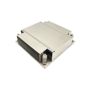
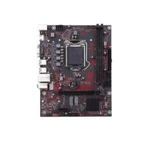
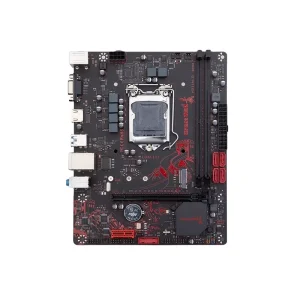
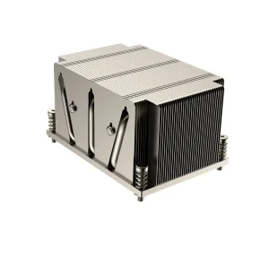
Explore our elite range of high-performance printed circuit board prototypes, server-grade heat dissipators, and advanced hardware structures.

In modern electronic engineering, thermal management is no longer a secondary consideration; it is a fundamental design driver. As components decrease in size and increase in power density, traditional FR4 substrates fall short due to their low thermal conductivity (~0.25 W/m·K). This technical bottleneck has driven the global adoption of Aluminum Circuit Boards—also referred to as Metal Core PCBs (MCPCBs) or Insulated Metal Substrates (IMS).
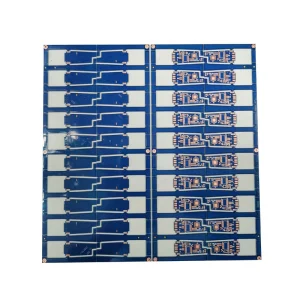
By substituting standard fiberglass substrates with highly thermally conductive aluminum alloys (typically Al 1060, 5052, or 6061), engineers can efficiently draw heat away from active semiconductor junctions. This white paper details the design parameters, manufacturing methodologies, supply chain dynamics, and emerging technological trends within China's top-tier Aluminum PCB fabrication industry.
The global demand for Aluminum PCBs is expanding rapidly, fueled by growth in automotive electrification (EV traction inverters, onboard chargers, LED headlamps), industrial automation, solid-state lighting, and high-density computing systems.
Sourcing from China's leading Aluminum PCB factories offers global OEMs significant advantages:
An Aluminum Circuit Board is not a single element but a complex, laminated composite comprising three primary functional layers:
| Material Parameter | FR4 Substrate | Standard MCPCB (Aluminum) | Advanced Thermal IMS |
|---|---|---|---|
| Thermal Conductivity | 0.25 W/m·K | 1.0 - 2.0 W/m·K | 3.0 - 8.0 W/m·K |
| Dielectric Breakdown Voltage | > 40 kV | 3 - 6 kV AC | 6 - 10 kV AC / DC |
| Thermal Impedance (Rth) | ~ 0.9 °C·in²/W | 0.2 - 0.4 °C·in²/W | 0.03 - 0.1 °C·in²/W |
| Coefficient of Thermal Expansion (CTE) | 14-17 ppm/°C (XY) | 22 ppm/°C (Base Aluminum) | Controlled CTE Options Available |
| Maximum Operating Temp (Tg) | 130 - 180 °C | 130 - 150 °C | 150 - 180 °C (High Tg) |
With the rapid adoption of electric vehicles, thermal stability has become paramount. Aluminum PCBs are deployed in onboard chargers (OBC), Battery Management Systems (BMS), DC-DC converters, and motor drive controller systems. They withstand extreme vibrations and deliver continuous, high-current heat dissipation.
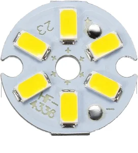
LED efficiency drops and degradation accelerates as junction temperatures rise. Aluminum PCBs are the industry standard for high-luminosity architectural lighting, streetlights, commercial displays, and medical surgical luminaires. They ensure continuous thermal transfer, preventing color shift and extending LED operating life.
High-efficiency power supplies, solid-state relays (SSRs), industrial inverters, and telecom amplifiers utilize Aluminum Clad boards to limit localized heating. By keeping power transistors, MOSFETs, and diodes operating within safe temperature ranges, system reliability increases exponentially.
As electronic design complexity rises, the industry is transitioning from simple, single-sided Aluminum PCBs to more sophisticated, high-density structures:
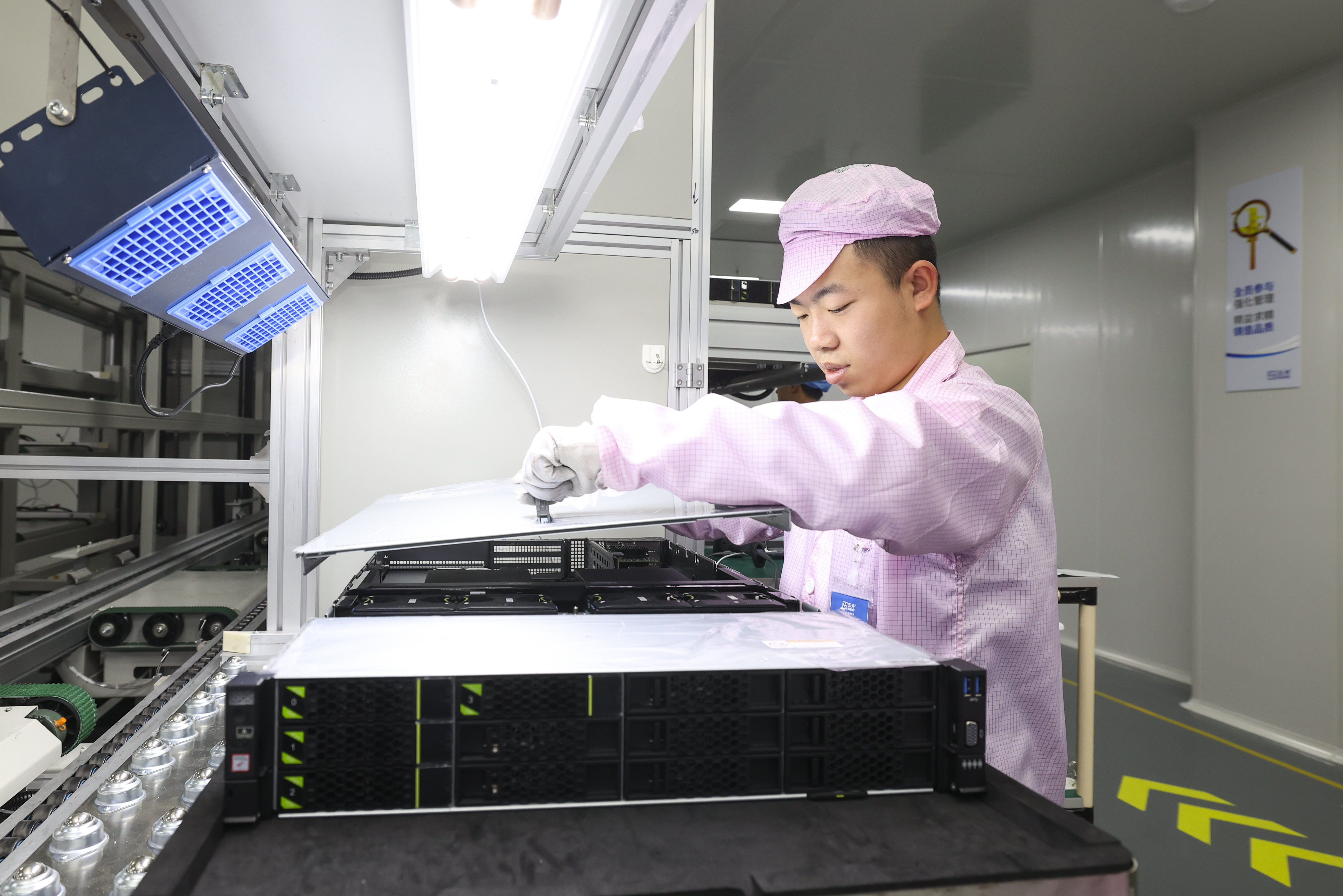
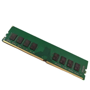
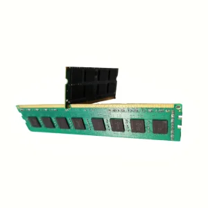
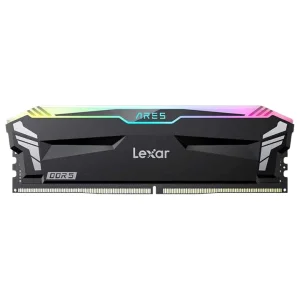
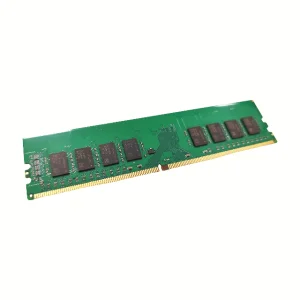
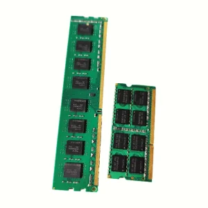
CoreByte Storage Technology Co., Ltd., established in 2016, stands as a specialized leader in engineering high-performance memory modules and thermal management hardware structures. Leveraging over 9 years of industry experience in high-speed, high-density semiconductor substrates, CoreByte has translated this expertise into the design and production of ultra-stable thermal printed circuit boards.
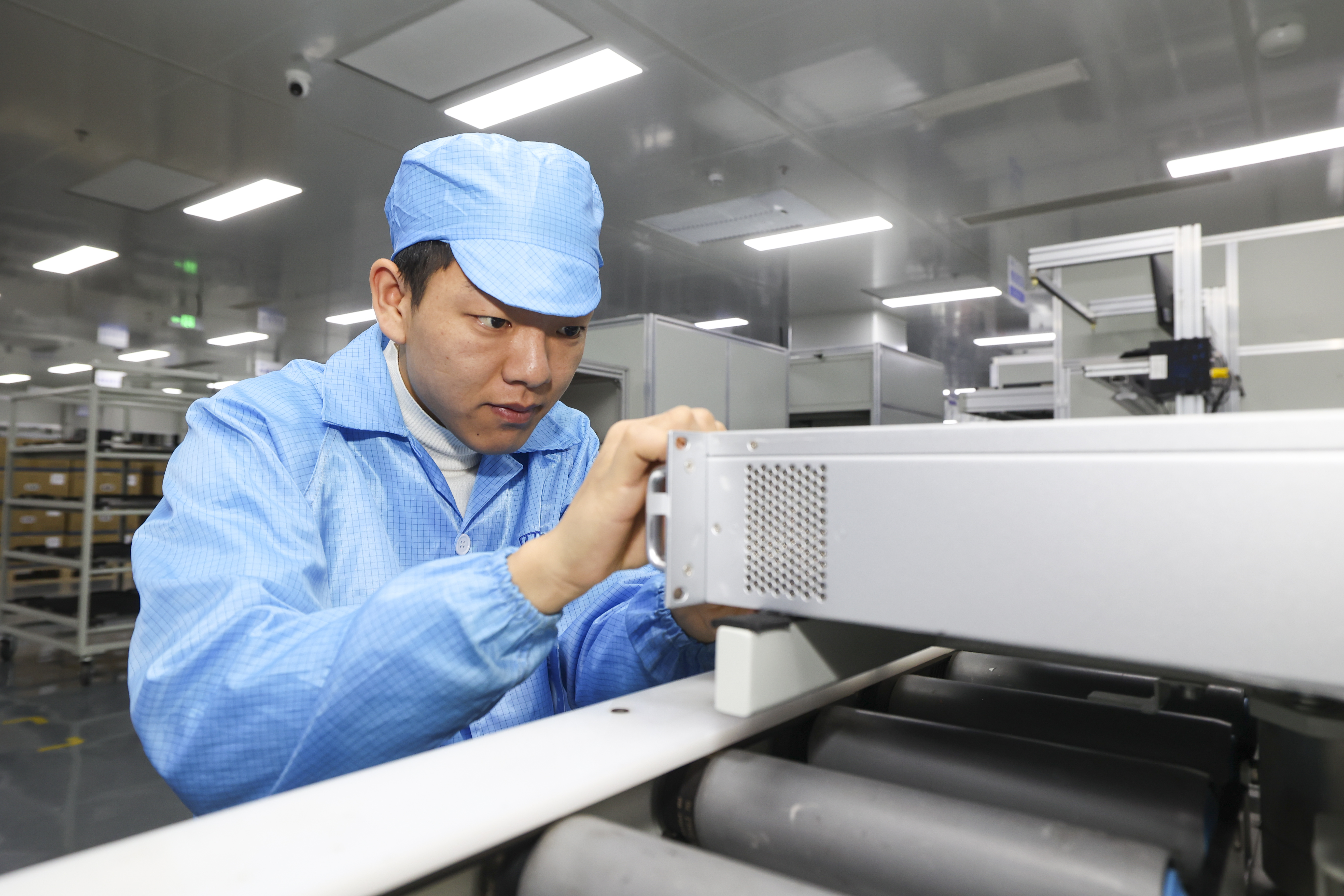
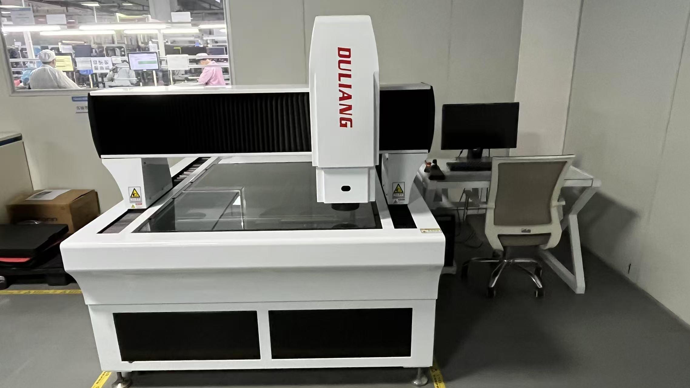
Operating within a highly optimized 320㎡ modern facility, the company maintains strict ISO9001-based quality management systems. Our production lines integrate state-of-the-art Automated Optical Inspection (AOI) and rigorous high-temperature aging test rooms. With 45 dedicated quality inspectors and an active team of 85 R&D engineers, CoreByte delivers solutions optimized for thermal performance, durability, and reliability.
Annually introducing approximately 120 new models, CoreByte serves a diverse client base across North America, Europe, Southeast Asia, and the Middle East, supported by over 1,200 supply chain partners. This strong semiconductor background guarantees that our metal core and multi-layer board designs conform to rigorous signal integrity and heat dissipation standards.
To ensure smooth integration into global commercial markets, our fabrication processes meet strict environmental and regulatory compliance codes:
Detailed answers to complex thermal design and manufacturing queries for engineering managers.
The dielectric layer represents the main thermal barrier in an Aluminum PCB. A thinner dielectric layer lowers thermal resistance, enhancing heat flow. However, it also reduces electrical isolation capability. Design engineers must strike a balance: for higher voltages (e.g., 220V AC or 400V DC EV systems), a thicker dielectric (e.g., 100µm to 150µm) with high dielectric strength is necessary. For low-voltage, high-current systems (e.g., 12V LED drivers), a thinner layer (50µm) is preferred to maximize heat dissipation.
For applications subject to mechanical stress or high vibrations, such as automotive engine bays or industrial machinery, Al 5052 is recommended. It offers a tensile strength of approximately 210-260 MPa, which is significantly higher than Al 1060 (typically around 60-100 MPa). For structural frames requiring maximum rigidity and thread-tapping strength, Al 6061 is preferred.
During thermal cycling, different expansion rates can strain solder joints and the dielectric interface. High-quality manufacturers mitigate this by utilizing specialized elastomeric or ceramic-filled resin dielectrics that act as a stress-absorbing buffer. Furthermore, using a optimized reflow profile and high-ductility copper foils prevents delamination and trace fracturing under thermal cycling testing (-40°C to +125°C).
The choice of surface finish depends on the assembly process. **HASL (Hot Air Solder Leveling)** is cost-effective but can yield uneven surface topography, which is less ideal for fine-pitch SMD components. **ENIG (Electroless Nickel Immersion Gold)** is highly recommended for advanced components due to its flat surface, excellent solderability, and long shelf life. **OSP (Organic Solderability Preservative)** is an excellent, cost-effective alternative for high-volume assemblies.
Discover our comprehensive range of high-efficiency processing motherboards, server coolers, and advanced semiconductor memory elements.
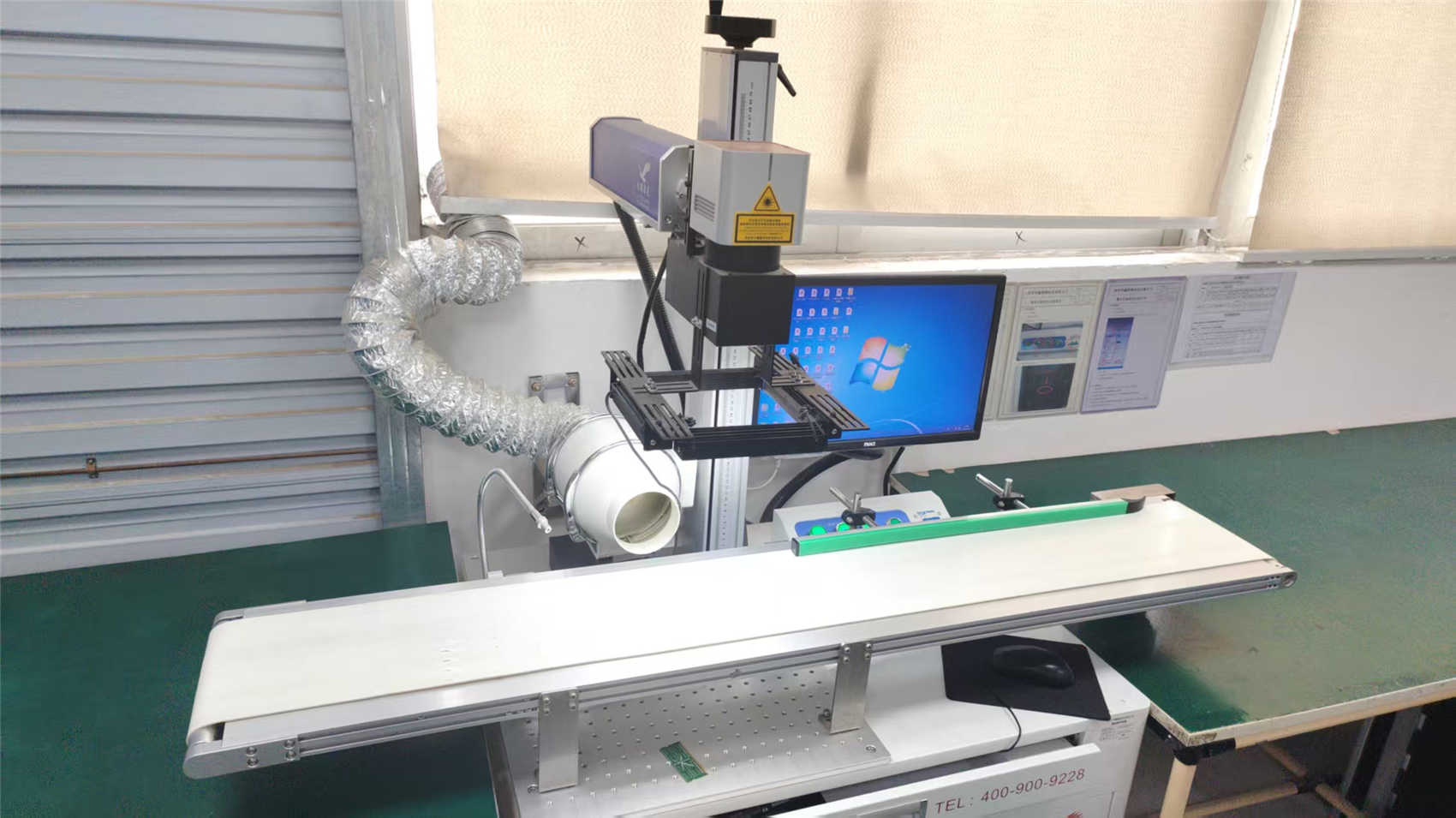
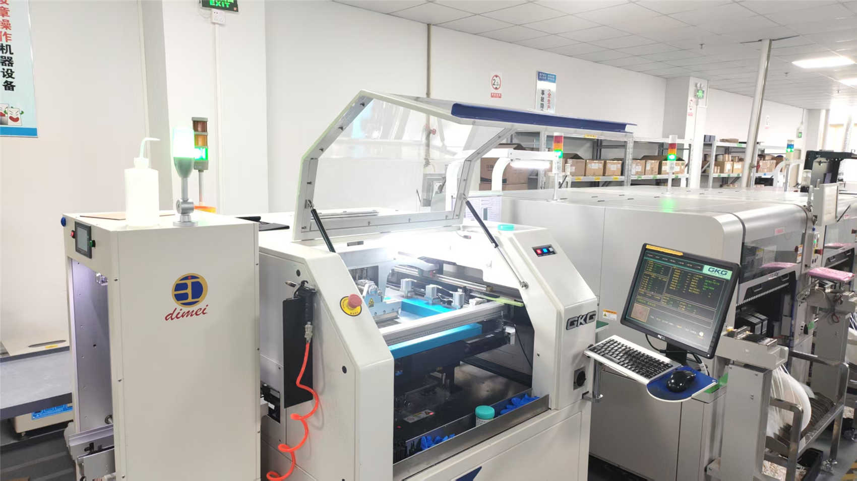
Visual tour inside our fabrication lines, research laboratories, and product testing areas.